Ic 4017 Led Circuit Diagram / 10 Led Roulette Circuit Using Tc4011 Lm4017 : Application led chaser circuit using ic 4017 and ic555.. Mr pin (pin 15), enable or clock inhbit pin (pin 13) is directly connected with ground and clock pin of counter directly connected with output pin of 555 timer. The ic has 10 yield outputs which are q0 to q10. This is led chaser circuit diagram using two 4017 in cascade.this is led chaser circuit using 4017 and 555. There is a casino game and a french word accompanying it called roulette. In the end, you can say the ic 4017 is one of the most flexible counters out there.
This circuit can work on voltages from 4.5v to 16v. What are the features of ic 4017? Plus, it's easy to make and includes a counter as well as a decoder. When it to pin 11 the output light will back to pin 3 and continue to glow in. This clock signal goes into the clock input of the ic 4017.
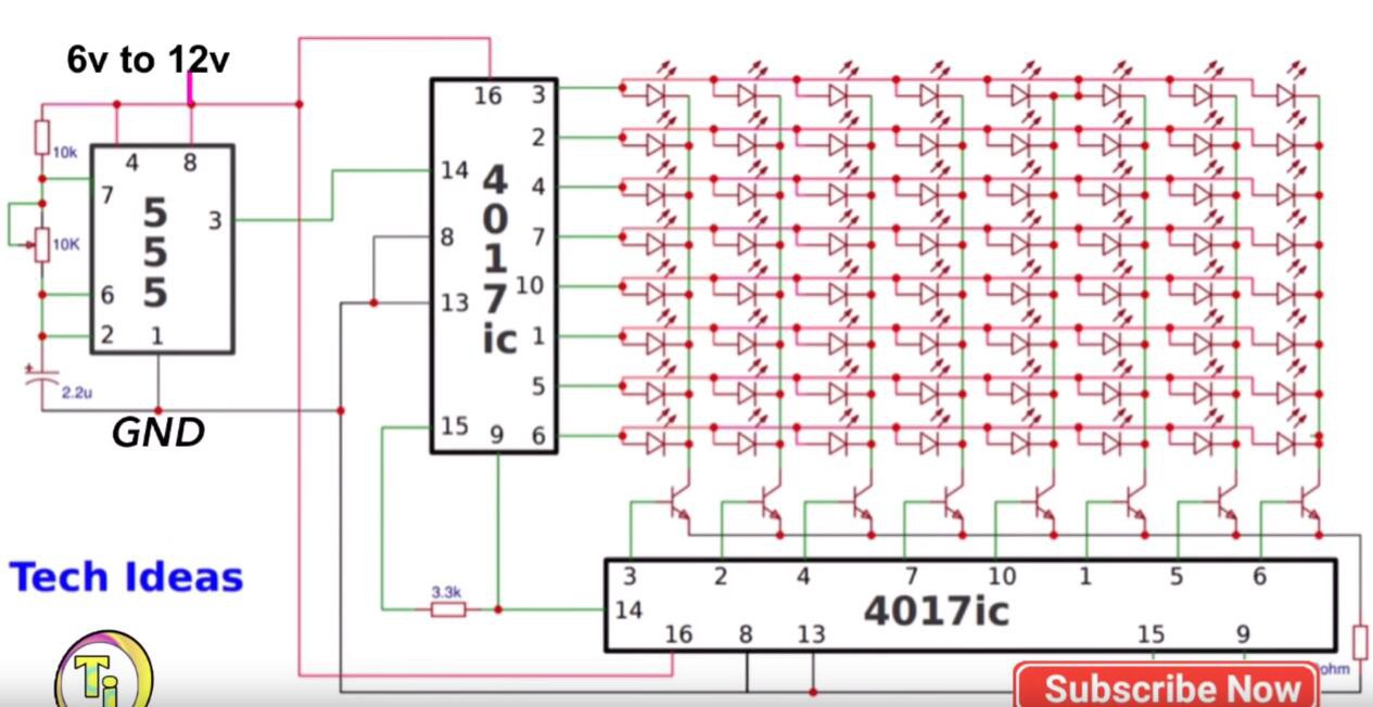
Running Led Matrix With Dual 4017 Ic Hackaday Io from cdn.hackaday.io We can adjust the pwm pulses by rotating the potentiometer. At pin 14 input clock pulse provided using the 555 timer ic. Takes a single input and converts it to different outputs. Plus, it's easy to make and includes a counter as well as a decoder. In the end, you can say the ic 4017 is one of the most flexible counters out there. The application is about led chaser circuit which works specifically by suing this johnson's counter divide by 10 ic 4017. Mr pin (pin 15), enable or clock inhbit pin (pin 13) is directly connected with ground and clock pin of counter directly connected with output pin of 555 timer. Moreover, the circuit is excellent for running led projects.
Here, the 555 timer provides the pwm pulses for running the 4017 ic.
The 100nf capacitor (c1) with the potentiometer (r2) wired as an adjustable resistor set the frequency of the oscillation. Basic ic 4017 pinout connection diagram. Led sequencer / chaser using ne555 & cd 4017 | circuit diagram. See more ideas about electronics circuit, circuit, circuit diagram. It can produce output at the 10 pins sequentially, i.e. Pins 4 and 8 of the 555 timer ic i.e., reset and vcc are connected to supply, which can any voltage between 9v and 12v. In this 4017 project, i have explained how to make a clap switch circuit using 4017. Look at the figure below is a block diagram of inside ic 4017 / hcf4017. In this electronics project, i have shown how to make an led chaser circuit with only 4017 ic. Find every electronic parts on octopart. Clap switch circuit using ic 4017. The ic will initiate every one of its output in a succession way when each time a positive pulse gets on its clock input pin 14. It seems we missed this one of the most popular applications of the ic 4017.
In the end, you can say the ic 4017 is one of the most flexible counters out there. 4017 ic is a cmos counter/divider integrated circuit, actually a decada counter with 10 decode ouputs. For this led chaser circuit, we have used all the 10 outputs of 4017 ic. In this 4017 project, i have explained how to make a clap switch circuit using 4017. And also use to build all kinds of the timer, led sequencers and controllers circuits.
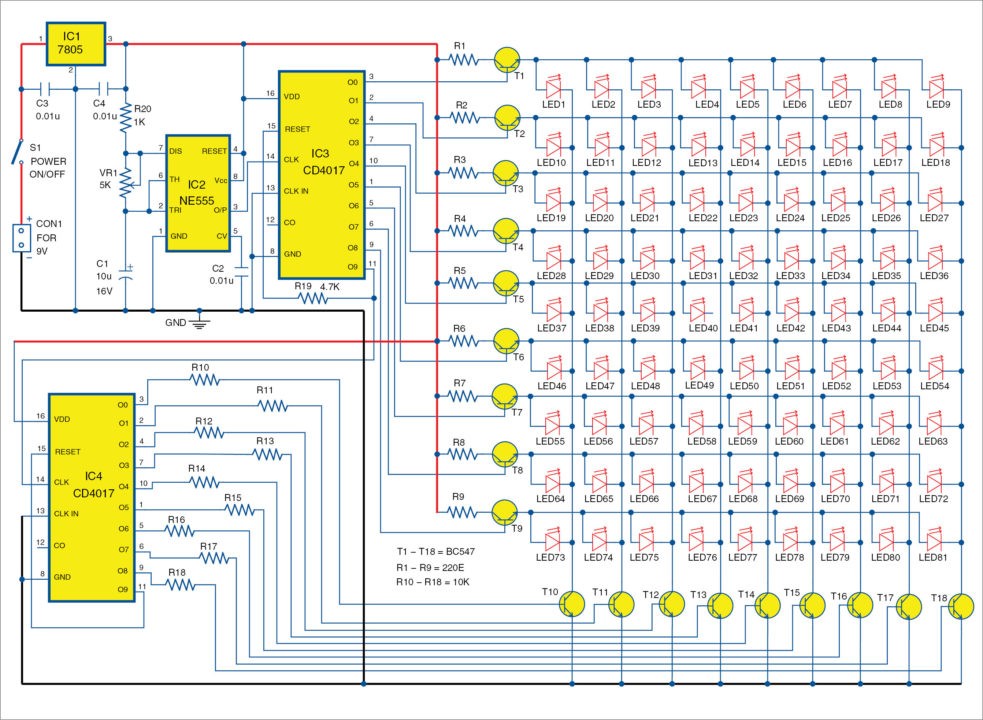
Led Sequencer Chaser Using 555 4017 Ics from circuits-diy.com Circuit diagram of 2 way 12 led running lights using cd4017 and ne555. This 10 different outputs can be used to run any external loads such as leds. The 1st and the 6th led will be directly connected to the ic4017. Pins 4 and 8 of the 555 timer ic i.e., reset and vcc are connected to supply, which can any voltage between 9v and 12v. Ic 4017 circuits and projects for hobby electronist and school. One of the best and simple applications of this 4017 counter ic is led flasher in sequence wise. Here you will find a collection of cd4017 circuits. Find every electronic parts on octopart.
The ic has 10 yield outputs which are q0 to q10.
The 1st and the 6th led will be directly connected to the ic4017. The application is about led chaser circuit which works specifically by suing this johnson's counter divide by 10 ic 4017. Decoding and control are by 16 inverters and 15 gates. You can see that the 555 timer wired as an astable multivibrator and its output is connected to the clock input of 4017 counter ic. Here is a circuit of a led sequencer / chaser using cd 4017 and ne555 ic. The ic has 10 yield outputs which are q0 to q10. Moreover, the circuit is excellent for running led projects. It seems we missed this one of the most popular applications of the ic 4017. Clap switch circuit using ic 4017. Here the flashing rgb led will generate the clock pulse for cd4017 ic. For this led chaser circuit, we have used all the 10 outputs of 4017 ic. An led chaser or led running light can be used as a decorative light, fancy light, chasing taillight for vehicles, etc. A 555 timer is set up in astable mode, which makes it into an oscillator circuit that creates a clock signal.
It can produce output at the 10 pins sequentially, i.e. Which its output glowing will slide down each position, by begin from output at 1 is pin 3, 2, 4, 7, 10, 1, 5, 6, 9 and 11 in sequence. Now, if i clap again the switch will turn off. There is a casino game and a french word accompanying it called roulette. It can count from 0 to 10 (the decade count).
Cd4017 Based Led Light 81 Led Chaser Light Full Project from electronicsforu.com It can produce output at the 10 pins sequentially, i.e. One of the most popular hobbyist projects to build with this chip is the running leds circuit. A number of different chser circuit are covered under this post, which. The cd4017 is a cmos decade counter ic. This ic gives 10 outputs according to the clock pulse it receives from the clock input, which is pin 14. The leds lights one by one for a period To make this simple led chaser circuit i have used only a 4017 ic. In this case it makes 10 different output.
To get a forward reverse effect using one 4017 ic we need to connect 8 diodes to the circuit.
Which its output glowing will slide down each position, by begin from output at 1 is pin 3, 2, 4, 7, 10, 1, 5, 6, 9 and 11 in sequence. I have used rgb flashing led instead of 555 timer ic to genera. In this 4017 project, i have explained how to make a clap switch circuit using 4017. Here, the 555 timer provides the pwm pulses for running the 4017 ic. Takes a single input and converts it to different outputs. If you worked on 555 timer pwm related projects, then the 555 part of the above circuit will be a familiar one. The cd4017 is a decoder ic it. I designed a pcb for 555 led flasher circuit using 4017 ic. For this led chaser circuit, we have used all the 10 outputs of 4017 ic. Here the flashing rgb led will generate the clock pulse for cd4017 ic. Here the outputs are connected to leds for indicating the sequential shift of the logics in. It can be adjusted to give the desired It can produce output at the 10 pins sequentially, i.e.
Share
Post a Comment
for "Ic 4017 Led Circuit Diagram / 10 Led Roulette Circuit Using Tc4011 Lm4017 : Application led chaser circuit using ic 4017 and ic555."

Post a Comment for "Ic 4017 Led Circuit Diagram / 10 Led Roulette Circuit Using Tc4011 Lm4017 : Application led chaser circuit using ic 4017 and ic555."